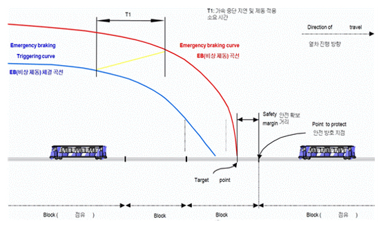
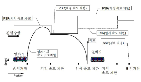
As a system based on on-board calculation with the medium concept between the existing ATC velocity code fixed block system and movable block system, ATC train control method is currently used for Metro9 based on the distance-to-go method. This system regularly detects and controls a train’s characteristics for acceleration and braking. Depending on the ground operation conditions such as the location of an earlier train, the system precisely calculates a train’s travel range on a track circuit, figures the train’s velocity directly and automatically. Through this process, the system helps to control and operate trains in a swift and safe manner depending on any changes in the conditions ahead.
Distance-to-Go Method
As a train receives ground information from a track circuit and beacon, such as location of an advanced train, condition of a traffic light and switch ahead, and data for each section, the train combines its own information data and accurately modifies the location of operation on the track through a location beacon.
Characteristics of various facilities
Signal
As a device to inform an engineer of whether a train can be operated, it receives the following absolute safety conditions from a linkage device and displays a signal to identify the entrance into a protection area visible by the naked eye.
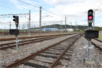
- Red(R) : Stop
- Yellow(Y) : Proceed conditionally (=indication of route opening)
- Applied to the branching portion of the ATC section (main line section), the Y signal appears when the line switcher is closed and the ATC blockage management section is unoccupied.
- When operating in ATP/ATO mode, adhere to the limitations imposed by on-board signaling equipment.
- When operating In RM mode, visually inspect the signal before proceeding.
- Green(G) : Proceed signal (=shunting signal)
- Applied to non-ATC section (garage) shunting signal
- G signal given when the turnout is locked, and the safety of the corresponding track is secured.
- Proceed according to the the yard mode (or RM mode) operation handling procedure.
Electric Point Machine or Switch
When it is necessary to change the operation direction of a train, it is used to shift the direction of a track. Until the train passes, it is locked mechanically and electrically to safely secure the path.

Electronic Interlocking
As a device to control the train’s path automatically and enable a train to operate safely, it composes a linked logic circuit with an electronic circuit by using a microcomputer and records and saves the duplex configuration of central processing unit (CPU), system’s self-diagnosis function, and controls disorder to ensure a remarkable level of reliability, stability, and maintenance.

- Important interface between signaling equipment and station equipment
- Interlocking with major devices (railway switch, signal, PSD, etc.)
- Transmission of bidirectional status information between ground ATC and local ATS
- Design based on safe-side operation (fail-safe principle)
- Guaranteed safe train operation
- Increased operational efficiency and railway capacity
- Simplicity of operation and management
Automatic Train Control
As an automatic train control device, it transmits train operation conditions such as the condition of a path ahead and data regarding the location of an advanced train and enables automatic operation without any ground signals.

Smartway Digital Track Circuit
As a solid state system, SDTC performs the function of transmitting information between track and train within the single track circuit (TC) with regard to safety issues such as train detection and track continuity detection. For the output of SDTC train circuit, a user system receives vital logic signals, which are equivalent to occupation or non-occupation of the track circuit.
Total Traffic Control System
As a device to comprehensively manage train operations, this system intensively detects on-site signal facilities, controls the path, and sets the automatic path based on schedule at the control office. As it is composed with redundancy to achieve safety and continuity, the system is able to have peak detection transfer switch. Despite any disorder in the system, the TCC computer can be changed to address a barrier during system operation.
Interface Computer
As a facility in the signal machinery office, IFC is installed in the office and performs the function of sending and receiving information between electronic linkage devices, ATP/ATO devices, and local facilities. Through the main transmission network, it plays a role as an information interface device which conducts the function of sending and receiving information between TCC and signal machinery office. IFC is composed of a redundancy system for reliability and continuity.
Train to Wayside Communication
As a device to transmit information between a vehicle and the signal machinery office, it identifies the location and queuing of trains through a beacon, sends and receives information on opening and closing PSD, and transmits a variety of data necessary for automatic operation through SDTC.

- Continuous transmission of information from track to train
- Onboard data delivered to ground ATC via downlink beacon